Introduction
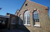
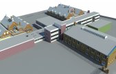
This case study relates to a complex of buildings that made up a mixed gender secondary school in London. When the existing school relocated to new built premises, the existing collection of buildings was sold to a local academy with plans to modernise the existing structures and reopen as a free school. The complex consists of a matching pair of triple bay Victorian-era school houses along with a modern modular multi-storey building and large sports hall. Greenhatch Group was commissioned to carry out a full measured building survey of the buildings once the current school had relocated, with the final output being a BIM model to be used as the basis for a series of works intended to modernise and refurbish the existing school buildings. The scope included the production of 3D models of all buildings on site along with a topographical survey, also presented as a 3D element within the final file.


Why was BIM Selected?
Not only was the final model to be used by the commissioning architects as a full measured building survey to act as a basis for their modernisation designs, but it was also to become a shared file between all disciplines involved in the construction and design works with various companies modifying the final file to produce a full design model integrating the designs from the architects, structural engineers and interior designers. Once the building works were complete, the model would then continue to be used by the estates management team working for the school as an asset management tool. As this was made clear to us within the initial brief, we were able to incorporate key parameters within the project and nested families that would aid this process once the model had been passed on to the end user.
How was the project undertaken?
The on-site survey work was carried out with our standard method of using phase-based laser scanners to capture point cloud data for the external areas and principal open spaces in combination with the use of a total station to coordinate the scan locations by recording the centre points of at least 4 black and white checkerboard targets for each scan location as well as carrying out a full traverse of all areas of the buildings to accurately position the building’s geometry. These were backed up by traditional hand sketches and measurements with a full photographic record throughout. The topographical survey was carried out traditionally using a total station and detail pole to create a full 3D surface that could be imported directly into Revit. We used Leica Cyclone in conjunction with Autodesk Recap to process the scan data into a format compatible with Autodesk Revit. The complete package of data facilitated the creation of a full LOD 350 model of all buildings within the site.
Once all data was processed and set to Ordnance Survey coordinates basic layout plans were created in AutoCAD to form the basis of the model creation. As AutoCAD handles real world coordinates far more accurately than Revit, we find it advantageous to produce basic plans for the site into which the model can be exported to confirm the accuracy of the location of the final model. Due to the internal 20km limit built into Revit, two site locations are created: a local grid where a physical permanent station marker on site is set to 0,0 and another at real world coordinates. All modelling is carried out on the local coordinates to ensure that the survey data displays at the correct location before the model is set to OS coordinates for exporting to AutoCAD and being issued to the client.
What was the deliverable output?
There were multiple deliverable outputs as part of the final product. These included a full model in RVT and IFC formats along with a 3D DWG export. Sheets were also set up within the RVT file to show the individual floor plans along with typical sections and elevations of each structure within the site. A copy of all collected scan data was also issued to the client in both e57 and RCP formats to ensure compatibility with various systems. An interactive HTML file of the floor plans was also set up with links to TruViews of each scan location to enable the viewing of all collected data by parties without the capability of processing and hosting large 3D point clouds. All data was issued to the end users via USB along with being securely hosted on our internal servers with access set up for any involved parties.
We had been asked to ensure that the schedules could be set up for all items within the project, with particular attention paid to the Victorian era windows and glazing. Typically, within Revit the individual windows can be quickly and easily scheduled by type or other constraint, however in this case the client requested that each individual pane of glass within the windows and doors could be scheduled to allow the model to be used for asset management and condition reports. To enable this a glass pane family was created that could be nested into each custom made window and door family with a shared parameter that would report back to the main model. Once complete, the window schedule consisted of over 2300 individually numbered glass panes allowing each one to be updated with its current condition so a list of works and maintenance could easily be created.
What problems were encountered?
Due to the age of the main school buildings, the roofs had spread causing the exterior walls to bow outwards. Through discussions with the client, we set tolerances for the modelling of any vertical deviation and dealt with these elements in one of two ways. In areas where the deviation was within 30mm a text note was added to a Survey Notes parameter built into each element that would specify the true deviation. The walls would then be modelled as vertical based on their position at a cut point of 1500mm up the face of the wall. Where the deviation from plumb was greater than our 30mm cut off point, the wall would be modelled with a thickness equaling the true wall depth plus the amount of deviation. A face based wedge shaped void was then applied to the internal and external face of the walls resulting in a wall with trapezoid geometry that would accurately follow the point cloud. Carrying out the modelling in this way as opposed to using a model in place or massed object ensured that the wall still functioned as a wall within Revit, allowing for the hosting of architectural elements and correct scheduling.
Timescales and Data Sizes.
The size of the project and the number of buildings on site meant that we required 12 days on site to fully capture scan data suitable to use as a base for the model. The collected data was processed and issued to the client along with basic 2D layout plans within a week with the full modelling of the site including topographical survey in around 4 weeks utilising multiple Revit technicians. The final issued model was an 85MB file, accompanied by scan data in RCP format split into individual floors and buildings to maintain usability totaling 15GB, together with an interactive HTML-based TruView of 14GB.